Context Switching
In the TriCore, there are two contexts, upper and lower. This just refers to the higher and lower numbered core address and data registers. On interrupts for example, the upper context area is automatically saved off in a Context Save Area which has 16 words of space for the 16 registers that are saved.
The lower set you have to handle yourself, but this is a good place for global variables or a way to pass arguments to other functions.
Traps
A trap is a system function that is called when certain signals are sent to the processor, such as system level signals like SIGTERM in Unix. Ctrl + C on a Linux shell is a good example of a trap being invoked. Traps do not typically have critical response time requirements, whereas interrupts often do.
Classically, a trap is just another way of saying exception or fault and are triggered when there is an undesirable or unexpected state of the CPU. Traps are used in the TriCore when there is some kind of internal failure such a context management or memory management error. There are various classes of traps, and specific errors within each class. Each class has it's own trap handler function. A set of trap handler functions may be considered to be part of a BSP.
Traps may be synchronous, asynchronous, hardware, or software sourced.
Recall that the interrupt and trap tables also take up memory and live in the core memory or flash. These tables are just a little bit of code that send you to the larger ISR handler functions you’ve written, and the index mechanism into the tables determines where each interrupt causes execution to go to get itself handled. The table locations are defined in the linker script.
For the Aurix processor, there is a register that records trap events on external input lines. Another register lets you define which cores will receive each trap event, which can go out to all cores simultaneously as the default. SW can then clear the trap flags after service.
Multi-Core Considerations
Here’s a bit of a puzzle: if a single core application has one single program entry point called main, then how many entry points does a multi-core application have? The answer is still one, for the simple reason that there can only be one matching definition for any function declaration.
MC procs often have independent clock divider registers for each core, so you can divide down the frequency of each core as you wish. In the Aurix there is also a simple timer module for each core, so you can use this as your system tick and each core will need one.
When loading/debugging multi-core, many debuggers support various program loading options:
- One executable for all cores, combined in a single binary file.
- Separate executables for each core, combined in a single binary file.
- Separate binary files for each core.
For the first option, the code is all loaded into one core's program flash and every core runs that code. The global variables live in the CPU local memory for that main core and are accessed by other cores. Trap and interrupt tables also reside in the main core program flash.
How do you build for multi-core?
The toolchain may give you the option of specifying core in the source code:
#pragma section ".text.main" axc0 2
static void main core 0 sub(void);
void main core0(void)
{
...
}
#pragma section
Or you may have a linker command argument for a given object file to indicate which core it is assigned to, such as --core=CPU<x>. Note that symbol visibility is a big architecture concern here and whether or not global symbols are accessible by other cores or not. You may have an option to hide all symbols except those indicated in an export-description file, and specified with a linker command like --export=<interface.c file>.
Program location is handled in the linker script.
GNU Multi-core Workflow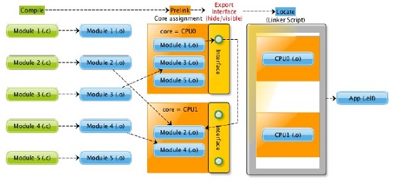
In case of single-core the linking is done in two steps. The first is the pre-linking where sections of input objects are collected into output sections and the second is the locating where output sections are located to memory regions. In case of multi-core the linking phase is extended with one addition step and one step is slightly modified. In the pre-linking phase a dedicated core can be assigned to the output object and exported symbols that are visible for other CPUs can be defined by an interface script. The linker stores this meta information for the sections and symbols, and checks its consistency as well. The pre-linking and core assignment can be iterated arbitrarily many times to group the objects and build a hierarchical structure.
While all this multi-core related information can be set on link time, we are able to migrate existing single-core applications to multi-core without modifying the source code.
The linker is able to link objects of different architectures together, therefore we can build one elf file even for heterogeneous multi-core architectures. For example ld core0.o core1.o core2.o mcs.o -o.
The protection of data access across cores is mandatory in a multi-core application. Interfaces can be defined with interface scripts, where you can define exported symbols. Only the exported symbols will be visible from the other cores. In the interface script you can also rename the symbols to match interfaces. In this case the symbol will be accessed locally by its original name and globally by its alias. Cross references between cores can be validated by the map file. The cross reference table of the map contains global symbols and all the objects with core information, where they are referred.
The linker adds core flags to the sections and symbols that are assigned to a core. This meta information is used in the linker for checking consistency of core assignments. The sections that are assigned to a core get a prefix .CPU<N> where <N> is the index of the assigned core. The following example shows a part of readelf output for a multi-core elf file. In case of section headers the core flags are 0 and 1, while they are CPU0 and CPU2 at the symbols.
Section Headers:
[Nr] Name Type Addr Off Size ES Flg Lk Inf Al
...
[22] .CPU0.csa NOBITS d0003440 013440 000800 00 WA0 0 0 64
[23] .CPU1.fasttext PROGBITS c0000028 010028 000050 00 AX1 0 0 2
...
Symbol table ’.symtab’ contains 715 entries:
...
518: d0000000 4 OBJECT LOCAL HIDDEN [CPU0] 17 foobar
...
598: 9f001552 72 FUNC GLOBAL DEFAULT [CPU2] 34 init applproc2
The Hide-Visibility Concept
A clear interface across CPU domains is essential in the design of multi-core applications. When an application has a lot of interfaces, it can make the maintenance of the product difficult and expensive, due to the hardly predictable side effects of software changes. In addition the hiding of symbols supports data protection which can be useful for software sharing projects.
Hidden symbols can be accessed only inside the core, where they are defined. Visible symbols can be accessed globally. By default all the symbols are visible. We can build the interface of cores by using --export=<file> option, where the <file> contains the export definitions of symbols. In this case every symbol will be hidden, except the exported ones. Each line of this interface script is an export definition with the following syntax:
EXPORT <type> <name> [AS <exported name>];
<type> The type of the symbol. It can be OBJECT or FUNCTION.
<name> The name of the symbol.
<exported name> An optional global alias for the symbol. It can be referred by this name
on the other cores.
An example for interface script is the following:
/∗ The function foo can be referred from other cores as foo. ∗/
EXPORT FUNCTION foo;
/∗ The variable bar can be referred from other cores as shared bar. ∗/
EXPORT OBJECT bar AS shared bar;
Inter-core communication
Inter-core Messaging - theories, tools, suggestions
Automotive Considerations
A multiple-OS solution requires a core-to-core (C2C) communication module which is not part of the AUTOSAR standard specification. PXROS is an example that includes this C2C messaging; it's a multi-core OS solution. For ThreadX, you would have to create your own as it's designed to operate independently on a single core.
An average performance of about one instruction per cycle indicates a reasonable system configuration.
Interrupts in MC
Aurix example: There is one Interrupt Router for the TC397, so it functions globally with the interrupt vector table. ThreadX calls this the exception vector table. However, each CPU has it's own BIV register which points to the table, so there must be an init sequence for each core to set this up.
Three-Core Init Sequence Example
This uses an the Infineon MCD Demo bare metal application.
They use the single binary for all cores, with shared symbols. Core0 kicks everything off, each core has a start sequence, a timer, and a timer interrupt handler that gets registered. The LED control application code is shared and does not differentiate by core ID.
The sequence is:
_start:0
cstart:0
.main:0 = init_applproc0
LED_Init()
Start_Core(1)
THE REST IS NOT SEQUENTIAL NECESSARILY
_start:1
cstart:1
.main:1 = init_applproc1
main:1
core1_main LOOP
Start_Core(2)
_start:2
cstart:2
.main:2 = init_applproc2
main:2
core2_main LOOP
main:0
core0_main LOOP